#some set stuff
set echo
option quiet
mode one.dim

#the vertical definition
line x loc = 0     spacing = 0.02 tag = top
line x loc = 0.50  spacing = 0.02
line x loc = 2.0   spacing = 0.25 tag=bottom

#the silicon wafer
region silicon xlo = top xhi = bottom

#set up the exposed surfaces
bound exposed  xlo = top  xhi = top

#calculate the mesh
init boron conc=1.0e14

#the pad oxide
deposit oxide thick=0.075

#the uniform boron implant
implant boron dose=3e14 energy=70 pearson

#plot the initial profile
select z=log10(boron)
plot.1d x.max=2.0 y.min=14.0 y.max=20.0

#the diffusion card
diffuse time=30 temp=1100

#save the data
structure out=boron.str

#plot the final profile
select z=log10(bor)
plot.1d x.max=2.0 cle=f axi=f
The first lines in the input deck set some basic SUPREM-IV.GS options.
#some set stuff
set echo
option quiet
mode one.dim
The '#' character is the comment character for SUPREM-IV.GS. The entire line after the '#' is ignored. The echo flag is turned on. This instructs SUPREM-IV.GS to echo input lines after they are typed. This is useful when the output from the simulator is being redirected into a file, so the commands are in the output listing. The second command instructs the simulator to be quiet about what it is doing. The default option is verbose, but this prints far more information than is needed by the novice user. The final command specifies that the simulation will be done in one dimension. It is therefore necessary to specify only vertical grid information.
The next section begins the definition of the mesh to be used for the simulation. The section
#the vertical definition
line x loc = 0     spacing = 0.02 tag = top
line x loc = 0.50  spacing = 0.02
line x loc = 2.0   spacing = 0.25 tag=bottom
describes the locations of the x lines in the mesh. SUPREM-IV.GS, in one dimensional mode, defines x to be the direction into the wafer. In two-dimensional mode, x is across the wafer top and y is the direction into the wafer. This simulation is to be done on a one dimensional problem, therefore lines are only specified in the x direction. The first statement places a mesh line at the top of wafer, x coordinate 0.0 microns and tags the line as "top". The spacing is set to 0.02 mm. A line is placed at 0.5 microns which is the expected starting depth of the implanted profile. The spacing is set to 0.02 microns. Since the spacing between the first two mesh lines is the same, 0.02 microns, there will be mesh lines placed 0.02 microns apart between 0.0 and 0.50 microns. Finally a line is placed at 2.0 microns, which is greater than the depth of the profile after the anneal. The spacing here is set to 0.25 microns. In the case where spacings are different in neighboring lines, the spacing is graded between them. The distance between mesh lines near 0.5 microns will be 0.02 microns and the distance will get progressively closer to 0.25 microns as the mesh gets closer to 2.0 microns. The line statement fixes line locations in the mesh as well as the average spacing between lines.
The next two sections describe the device starting material and the surfaces which are exposed to gas.
#the silicon wafer
region silicon xlo = top xhi = bottom

#set up the exposed surfaces
bound exposed  xlo = top  xhi = top
The region statement is used to define the starting materials. In this case the wafer is silicon with no initial masking layers. The silicon area is defined to extend between the lines tagged top and bottom in the vertical direction. Looking back at the mesh line definition section, this corresponds to the entire area that had been defined. The initial simulation area is completely silicon.
The bound statement allows the definition of the front and backsides of the wafer. Any gases on the diffuse, deposit, and etch statements are applied to the surface marked exposed. It is important to define the top of the wafer for SUPREM-IV.GS to correctly simulate these actions. Most mistakes are made by ignoring to define the exposed surface.
The next line informs SUPREM-IV.GS that the mesh has been defined and should be computed.
#calculate the mesh
init boron conc=1.0e14
This statement computes the locations of lines given the spacings, triangulates the rectangular mesh, and computes geometry information. The initial doping is boron with a concentration of 1.0E14 cm-3.
The next line adds a pad oxide to the wafer.
#the pad oxide
deposit oxide thick=0.075
The deposited oxide is specified to 0.075 microns thick. This represents the pad oxide that is grown before the uniform boron implant. Rather than simulate the growth, it is simpler to add a deposited oxide the correct thickness of the pad.
The next statement performs the implant of the boron.
#the uniform boron implant
implant boron dose=3e14 energy=70 pearson
The implant is modeled with a Pearson-IV distribution. The energy and dose are 3.0E14 cm-2 and 70 KeV respectively. This produces an abrupt boron profile with a junction near 0.3 microns.
The next commands choose a plot variable and display it.
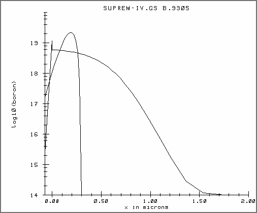
#plot the initial profile
select z=log10(boron)
plot.1d x.max=2.0 y.min=14.0 y.max=20.0
The plot will look like Figure 1. The select statement selects the plot variable to be the log base ten of the boron concentration. The plot.1d statement does not need to specify the location of the cross section in one dimension. The plot should extend between the minimum value of y through 2.0 microns. Dimensions on the plot command always refer to the plot axis. In this case, the x axis is the depth dimension, and the y axis is the log of the boron concentration. The minimum and maximum on the y axis are set to 1.0E14 and 1.0E20. The y axis values have to be specified in the units of the selected variable, log10 of concentration.
The diffuse command simulates the 30 minute, 1100C anneal.
#the diffusion card
diffuse time=30 temp=1100
The default ambient is inert, so no oxide will be grown. The diffuse command will produce the following output:
estimated first time step -0.000000e+00
Solving        0 +      0.1 =      0.1,      100%, np 43
Solving      0.1 + 0.488986 = 0.588986,  488.986%, np 43
Solving 0.588986 +   2.9165 =  3.50548,  596.438%, np 43
Solving  3.50548 +  5.36005 =  8.86554,  183.784%, np 43
Solving  8.86554 +  8.54232 =  17.4079,   159.37%, np 43
Solving  17.4079 +  3.80138 =  21.2092,  44.5005%, np 43
Solving  21.2092 +   12.795 =  34.0042,  336.588%, np 43
Solving  34.0042 +  15.4141 =  49.4183,   120.47%, np 43
Solving  49.4183 +  22.2639 =  71.6822,  144.439%, np 43
Solving  71.6822 +  28.0168 =   99.699,  125.839%, np 43
Solving   99.699 +  26.4923 =  126.191,  94.5586%, np 43
Solving  126.191 +  41.1269 =  167.318,  155.241%, np 43
Solving  167.318 +   29.629 =  196.947,  72.0429%, np 43
Solving  196.947 +  56.4872 =  253.434,  190.649%, np 43
Solving  253.434 +  60.4027 =  313.837,  106.932%, np 43
Solving  313.837 +  92.0295 =  405.867,   152.36%, np 43
Solving  405.867 +  103.787 =  509.654,  112.776%, np 43
Solving  509.654 +  73.6803 =  583.334,  70.9916%, np 43
Solving  583.334 +  175.487 =  758.821,  238.174%, np 43
Solving  758.821 +  205.108 =   963.93,  116.879%, np 43
Solving   963.93 +   265.71 =  1229.64,  129.546%, np 43
Solving  1229.64 +  376.381 =  1606.02,  141.651%, np 43
Solving  1606.02 +  193.979 =     1800,  51.5381%, np 43
The first line prints the estimate of the initial time step size. The message is informative only. Each of the following lines indicates a time step of the diffusion. The format is the current time + the size of the time step will equal the time after the step. The user can, therefore, determine exactly how far the simulation has proceeded. The next number is the size of the next time step, expressed as a percentage of the current time step. It can be seen for this problem that the time step increases regularly. The final bit of information is the number of points in the mesh, 43 in this example.
The next step is to save the data for further examination.
#save the data
structure out=boron.str
This saves the data in the file boron.str. This file can be read in using the initialize command or the structure command.
The following script will plot the final boron concentration.
#plot the final profile
select z=log10(bor)
plot.1d x.max=2.0 cle=f axi=f
The first statement picks the log base ten of the boron concentration to plot. The plot will be placed on the earlier plot. The "cle=f axi=f" instructs SUPREM-IV.GS to not clear and not compute new axes.
Figure 2 shows a deeper junction as expected, as well as segregation into the oxide. The spike at the surface indicates that the surface oxide concentration is about 20 times larger than the silicon surface concentration.