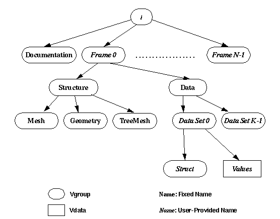
FIGURE 1 Hierarchical file layout for files conforming to HDF-V standard.
This document discusses VGeMesh (vee-gee-mesh), a file structure using HDF Vset as an efficient format for storing semiconductor simulation data sets. The purpose of the standardized format is to facilitate data exchange between various simulators and to provide an unstructured mesh representation that is usable by high-end visualization tools. The proposed format provides a minimal representation standard for unstructured meshes and geometry. The organization of data is designed to be flexible and to allow additional representations (e.g. tree-structured meshes, mask or process flow) to be added while still remaining backward compatible with existing applications. It should be emphasized that an application can use any of a number of different data structures to represent the structure and the fields on the structure. Typically, an application will store a geometry, an unstructured mesh , and several fields interpolated on the unstructured mesh. However, it may only store an unstructured mesh or only the geometry. The access mechanisms provided by HDF Vset provide easy and efficient retrieval of only the data that the simulation tool understands.
HDF Vset provides low-level hierarchical management of homogeneous data sets in a similar fashion to a Unix file system. The concepts of directories and files map into Vgroups and Vdata in HDF Vset. Actual data is contained in Vdata. Related Vdata are hierarchically grouped together to form Vgroups. VGeMesh defines the organization of the hierarchy and the naming conventions and data structures to be used to represent semiconductor simulation data.
It must be emphasized that this document describes a format that is fully extensible. Backward compatibility assures that any applications that use the standard will not be affected when a new representation is defined.
The general layout of a VGeMesh file is shown in

FIGURE 1 Hierarchical file layout for files conforming to HDF-V standard.
A VGeMesh file consists of a required Documentation Vgroup and a sequence of one or more Frame Vgroups. Each frame consists of a required Structure Vgroup and an optional Data Vgroup. The Structure Vgroup may provide an unstructured mesh, geometry, or a tree-structured mesh. The Data Vgroup is used for storing scalar and vector data defined at the nodes of a given unstructured mesh. The naming conventions for the Vgroups and Vdata in the hierarchy and data structures are discussed in detail in the following sections. These descriptions assume that the reader is familiar with the HDF Vset hierarchy and data access methods.
The following notation is used throughout this document: Bold typeface is used for predefined names. The context will indicate whether a name is for a Vgroup or a Vdata. For example, Documentation is a predefined Vgroup. Italics are used to indicate Vgroups or Vdata whose names are supplied by the application (i.e., they are not predefined). An example of such Vgroups is the Frame Vgroup.
The Documentation Vgroup provides a means of documenting both the entire file as well as any component of the data set. The top level, Frame, Structure or Data Vgroups may have a Documentation Vgroup contained within. A documentation Vgroup is identified as any Vgroup with class name Documentation. There are three predefined Vdata in the Documentation Vgroup - Name, Creator, and Notes. The first Vdata, Name, holds the name given to the data set and is limited to 255 characters. The second Vdata, Creator, holds the name and version of the tool that created the data set, and is intended to be used as a hint to the data sets contained within. It is also limited to 255 characters. The last Vdata, Notes, is open to a general description of the data, its simulation techniques, and any other information of general interest about the simulation data. It has no length restriction.
Any other Vgroup at the top level with class name Frame is a frame. Frames provide a means for sequencing of groups of simulation data. For example, in semiconductor process simulation, the frames may represent the state of the wafer after certain processing steps. At least one frame must be present and each of the frame Vgroups must have a unique name.
A Vgroup named Structure under a Frame Vgroup stores the meshes or geometry in each frame. A Structure Vgroup must have at least one Vgroup that is one of Mesh, or Geometry. The Mesh Vgroup will store an unstructured mesh and the Geometry Vgroup will store the structure's geometry.

FIGURE 2 HDF-Vset file hierarchy for Mesh Structure.
The Mesh Vgroup stores all information needed to store and construct an unstructured mesh. It contains Vdata that store the coordinates of the nodes in the mesh and their connectivity to form elements in the mesh. Optionally, it may contain a Vdata to contain local structuring (defined below). It may also contain any other Vdata or Vgroups to contain attributes that are necessary for persistent storage and retrieval of data. This includes material attributes for elements.
Vdata with the names PI, PJ, PK, and PL represent coordinates of the nodes of the mesh. PI, PJ, and PK, represent x, y, z coordinates respectively in a right handed coordinate system. PL is to be used for time. Numbering within a coordinate Vdata is required to start with zero (0).
An unstructured mesh is represented by an element list.
Each element consists of a set of points
that connect to form it. The name of the Vdata
containing the connectivity of each element is used
to determine the types of elements in the mesh.
A useful subset of Vdata names and meshes are
defined. They are as shown in
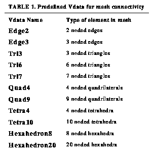
TABLE 1. Predefined Vdata for mesh connectivity.
The format allows for mixed meshes (i.e. meshes composed of several different types of elements), provided that
all elements are a degenerate case of
some higher order element, and are of the same dimension.
No distinction is made between surface or volume meshes.
Both can be represented using this format.
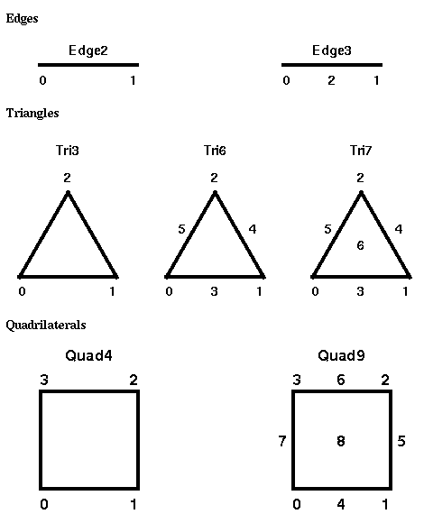
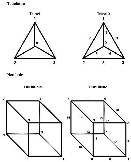
In the following figures, numbers refer to local nodes of
an element. Each connectivity list consists of a two dimensional
array of the number of elements by the maximum number of nodes per
element. Entries in this array are integers indexing into the
coordinate arrays, assuming that the first element in the
coordinate arrays is element 0. The connectivity is stored fully interlaced,
varying local nodes most rapidly. For a degenerate element, the
corresponding node is -1 (minus one). Although mapping of coordinates
is unspecified, the convention chosen should be consistent - always
clockwise or counterclockwise.
Auxiliary connectivity information may be used to store local
element structure such as neighbor information and boundary conditions.
As such, the Vdata
AuxiliaryConnectivity is predefined.
For 2D elements, this Vdata contains neighbors that share the
same edge. For example, if a quad is defined to be connected between
nodes 4, 9, 13, and 17. The AuxiliaryConnectivity Vdata for
the element will contain four entries corresponding to
element numbers that share the edge connecting each of:
nodes 4 and 9, nodes 9 and 13, nodes 13 and 17, and
nodes 4 and 17. This scheme
is illustrated in the example. For 3D elements, the neighbor number
semantics are defined in

TABLE 2. Element neighbor numbering semantics for tetrahedra meshes
and
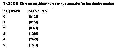
TABLE 3. Element neighbor numbering semantics for hexahedra meshes.
The faces referred to in the tables are defined by the element node numbering
in the element figures above. Furthermore, the number of neighbors for
each element is equal to the
number of edges or faces of the element. Thus, all
triangles (3 noded, 4 noded, 6 noded or 7 noded) have three neighbors.
If the element is along a boundary and does not have a neighbor, then
this Vdata entry can be used
to define boundary conditions. For process simulation meshes, the
neighbor numbers are used for specifying the commonly encountered boundary
conditions and are listed in

TABLE 4. Specification of boundary conditions in process simulation
For device
simulation, negative numbers for neighbors indicate electrode numbers
at the edge (without the minus sign). An electrode number of -1024
specifies an open electrode with an infinite resistance.
Neighbor information can be built from scratch from a fully unstructured mesh without a AuxiliaryConnectivity Vdata. However, for applications that do not store the geometry of the device, the AuxiliaryConnectivity Vdata is the only way to specify boundary conditions.
For both device and process simulation, elements are defined over
different materials. Material data are stored in a separate Vdata called
Material under the Mesh Vgroup. Common materials
and their corresponding material numbers are defined as in

TABLE 5. Predefined material numbers to be used in the Material Vdata.
Compound materials that have fractional compositions (e.g. Al x Ga 1-x As) need to store the composition in a separate Vdata. Thus, two Vdatas - MaterialXComposition and MaterialYComposition are predefined.
The example illustrated in
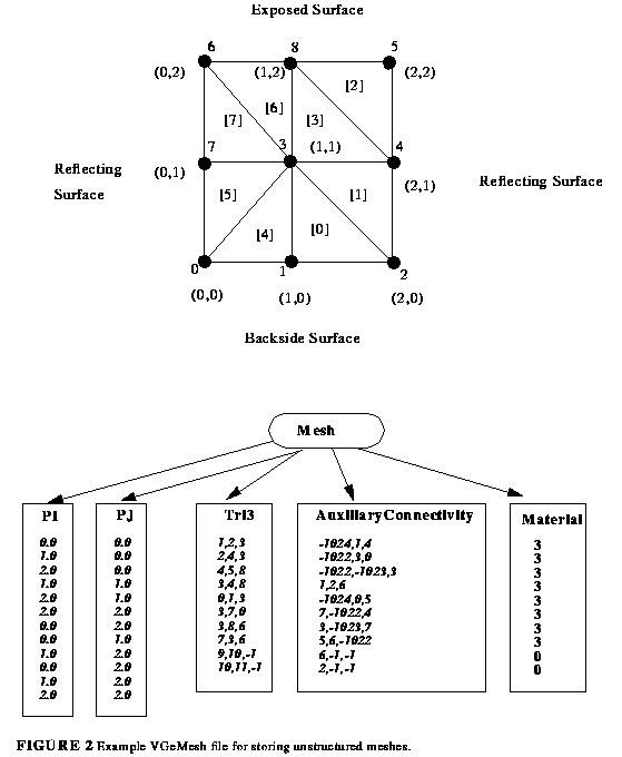
FIGURE 2 Example VMesh file for storing unstructured
meshes
shows the use of VGeMesh for storing an unstructured mesh.
Numbers within parentheses represent coordinate values. Numbers within
brackets represent element numbers. Numbers next to black dots
represent node numbers. Note the use of degenerate elements to store
solution values for Gas nodes. This is useful for storing ambient
concentrations of impurities for process simulation. However,
this scheme requires the use of elements to access
solutions because nodes in the coordinates list will be duplicated.

FIGURE 4 HDF-Vset file hierarchy for Two-Dimensional Geometry Structure
The geometry is defined as a hierarchy of points, edges, boundaries, and regions in 2D and points, edges, boundaries, surfaces and volumes in 3D. The following Vdata names are predefined for storing geometries: PI , PJ , PK , Edge , Boundary , BoundaryNoofEdges, Region, RegionNoofBoundaries, Volume and VolumeNoofRegions.
P I , PJ and PK are used to store the coordinates of the spatial points identical to their use in the Mesh Vgroup. Edge Vdata is an integer dataset containing indexes into the coordinates Vdata for the starting and ending points of an edge. There are thus two indices for each edge. Boundary Vdata ia an integer dataset that contains an ordered listing of edge indices that comprise the boundaries. Clockwise or counterclockwise sense of the ordering is left unspecified. Since a geometry normally contains many boundaries each with a different number of edges, a BoundaryNoofEdges Vdata is defined to act as an index into the Boundary Vdata. For example, if a geometry contains 3 boundaries with 34, 9, and 15 edges, BoundaryNoofEdges will be a Vdata with three elements: 34, 9 and 15. Region and Volume Vdata are defined similarly with the auxiliary Vdata RegionNoofBound aries, and VolumeNoofRegions . This scheme allows for a compressed sparse storage mechanism. Please see the example below for further elucidation.
Other Vdata may be defined as needed to contain other attributes of the objects that comprise the geometry. Materials are defined over regions and material data are stored in Vdata called Material. The format and numbering of the Material and optional MaterialXComposition and MaterialYComposition are identical to their use in the Mesh Vgroup. Boundary conditions are specified on edges using the predefined Vdata BoundaryCondition . The same numbering mechanism for exposed, reflecting and backside boundary conditions and electrode information is used as described for the Mesh Vgroup.
The example illustrated in
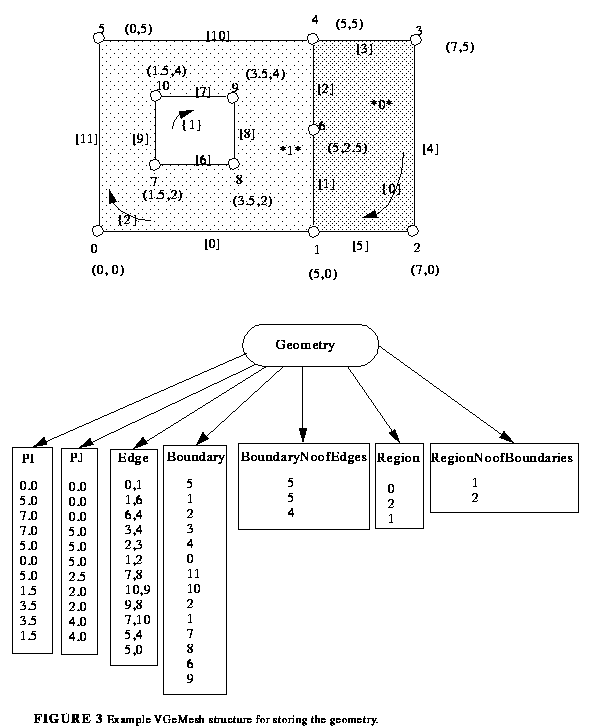
FIGURE 3 Example VMesh structure for storing the geometry
shows the use of VGeMesh for storing a geometry. Numbers
within parentheses represent coordinate values. Numbers next to
black dots represent node numbers. Numbers within brackets represent
edge numbers. Numbers within curly braces represent
boundary numbers. Numbers delimited by asterisks are region
numbers. There are two regions and region one has two boundaries.

Figure 5 HDF-Vset file hierarchy example for Tree Mesh
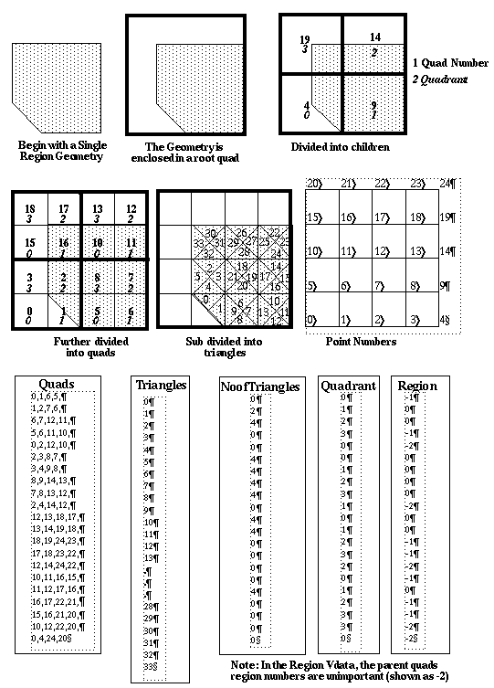
A TreeMesh is defined as a hierarchy of tree elements, the points which define them, the sub-elements which they contain, the Region in which they lie, and their Child-Number. In addition to the usual coordinate name PI,PJ etc., the following Vdata names are predefined for storing quad tree meshes: Quads, Triangles, NoofTriangles, Region and Corner. Here, Quads, would be the Tree Element, Triangles refers to the Tree Sub-Element, and Quadrant is used for Child-Number because it refers to the quadrant or corner a child quad occupies within the parent quad.
PI, and PJ are used to store the coordinates of the spatial points not necessarily identical to their use in the Mesh VGroup. The Quads Vdata is an integer dataset containing ideces into the Coordinates Vdata for the points that define a quad, ordered as shown in section 2.4.2.3. There are thus four indeces for each quad. The Triangles Vdata is an intefer dataset that contains indeces into the connectivity Vdata of the Mesh structure. Since a quad can contain varying numbers of Triangles, a NoofTriangles vdata contains the number of triangles in each quad similar to the Noof Vdata's in the Geometry structure defined above. The Region VData is an integer list of region numbers as defined and stored in theGeometry structure defined above. Regions of parents are unimportant.
Other Vdata may be defined as needed to contain other attributes of the objects that comprise the tree mesh.
Data is stored under a Vgroup named Data under a Frame Vgroup. It groups the data sets in each Frame . If present, a Data Vgroup must have at least one data set Vgroup.
A Data Set Vgroup is any non-Documentation Vgroup under the Data Vgroup. It must contain a Vgroup which is a link to one of the meshes in the same frame's Structure Vgroup. It must also have a Values Vdata containing values at the nodes of the given mesh. This Vdata must contain the same number of elements as the coordinate Vdata in the mesh. The names Scalar , Vector2 , and Vector3 are reserved for Values Vdata. Each of these contain floating point values. The vector types are stored fully interlaced and provide data consistent with the ordering of the coordinate axes (i.e. PI , PJ or PI , PJ , PK , respectively). Other value representations may be added (e.g. magnitude and phase for a complex number, tensors, etc.).
The following list enumerates predefined Data Set Vgroup names for quantities of interest in semiconductor device simulation. None of these is required.
NetDoping			TotalDoping
TotalDonorDoping		TotalAcceptorDoping
DonorTrapConcentration		AcceptorTrapConcentration
DonorTrapLevel			AcceptorTrapLevel
ElectronMobility		HoleMobility
NetRecombination		RadiativeRecombination
SHRRecombination		AugerRecombination
ElectricPotential		ElectricField
ElectronQuasiFermiLevel		HoleQuasiFermiLevel
ElectronLifetime		HoleLifetime
ElectronConcentration		HoleConcentration
ConductionCurrent		DisplacementCurrent
ElectronCurrent			HoleCurrent
TotalCurrent			LatticeTemperature
ElectronTemperature		HoleTemperature
DielectricConstant		ElectronAffinity
ConductionDensityOfStates	ValenceDensityOfStates
ConductionBandOffset		ValenceBandOffset
Composition			Bandgap
ImpactIonization
The following list enumerates predefined Data Set Vgroups quantities of interest in semiconductor process simulation. None of these is required.
InterstitialConcentration	VacancyConcentration
InterstitialTrapConcentration	ElectricPotential
ElectronConcentration		HoleConcentration
Velocity			Stress
In addition to the quantities listed above, impurity concentrations are named by either Impurity ActiveConcentration or Impurity ChemicalConcentration , where Impurity is the name of the element. For example, BoronChemicalConcentration and BoronActiveConcentration are Vdata for storing chemical and active concentration values of Boron.